Product Description
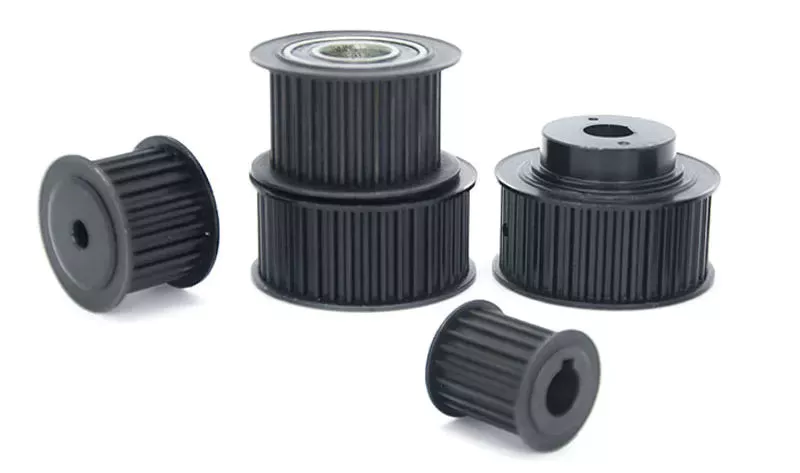
CHINAMFG Machinery offers a wide range of high quality Timing Belt Pulleys and Toothed Bars / Timing Bars. Standard and non-standard pulleys according to drawings are available.
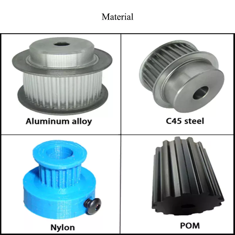
Types of material:
1. AlCuMgPb 6061 6082 Aluminum Timing Pulley
2. C45E 1045 S45C Carbon Steel Timing Pulley
3. GG25 HT250 Cast Iron Timing Pulley
4. SUS303 SUS304 AISI431 Stainless Steel Timing Pulley
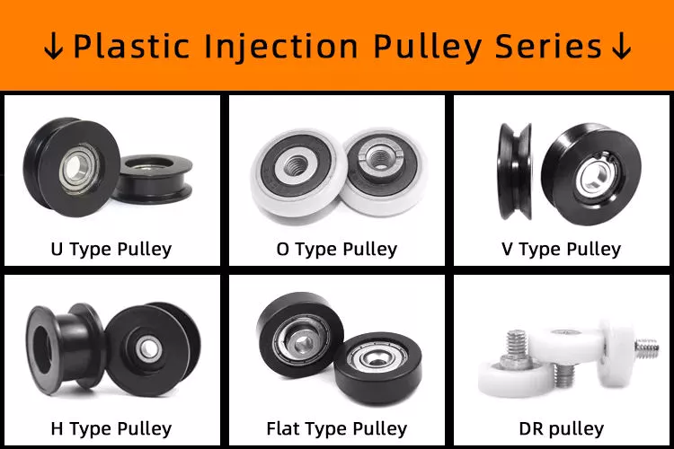
5. Other material on demand, such as cooper, bronze and plastic
Types of surface treatment
1. Anodized surface -Aluminum Pulleys
2. Hard anodized surface — Aluminum Pulleys
3. Black Oxidized surface — Steel Pulleys
4. Zinc plated surface — Steel Pulleys
5. Chromate surface — Steel Pulleys; Cast Iron Pulleys
6. Nickel plated surface –Steel Pulleys; Cast Iron Pulleys
Types of teeth profile
| Teeth Profile | Pitch |
| HTD | 3M,5M,8M,14M,20M |
| AT | AT5,AT10,AT20 |
| T | T2.5,T5,T10 |
| MXL | 0.08″(2.032MM) |
| XL | 1/5″(5.08MM) |
| L | 3/8″(9.525MM) |
| H | 1/2″(12.7MM) |
| XH | 7/8″(22.225MM) |
| XXH | 1 1/4″(31.75MM) |
| STS STPD | S2M,S3M,S4.5M,S5M,S8M,S14M |
| RPP | RPP5M,RPP8M,RPP14M,RPP20M |
| PGGT | PGGT 2GT, 3GT and 5GT |
| PCGT | GT8M,GT14M |
Types of pitches and sizes
Imperial Inch Timing Belt Pulley,
1. Pilot Bore MXL571 for 6.35mm timing belt; teeth number from 16 to 72;
2. Pilot Bore XL037 for 9.53mm timing belt; teeth number from 10 to 72;
3. Pilot Bore, Taper Bore L050 for 12.7mm timing belt; teeth number from 10 to 120;
4. Pilot Bore, Taper Bore L075 for 19.05mm timing belt; teeth number from 10 to 120;
5. Pilot Bore, Taper Bore L100 for 25.4mm timing belt; teeth number from 10 to 120;
6. Pilot Bore, Taper Bore H075 for 19.05mm timing belt; teeth number from 14 to 50;
7. Pilot Bore, Taper Bore H100 for 25.4mm timing belt; teeth number from 14 to 156;
8. Pilot Bore, Taper Bore H150 for 38.1mm timing belt; teeth number from 14 to 156;
9. Pilot Bore, Taper Bore H200 for 50.8mm timing belt; teeth number from 14 to 156;
10. Pilot Bore, Taper Bore H300 for 76.2mm timing belt; teeth number from 14 to 156;
11. Taper Bore XH200 for 50.8mm timing belt; teeth number from 18 to 120;
12. Taper Bore XH300 for 76.2mm timing belt; teeth number from 18 to 120;
13. Taper Bore XH400 for 101.6mm timing belt; teeth number from 18 to 120;
Metric Timing Belt Pulley T and AT
1. Pilot Bore T2.5-16 for 6mm timing belt; teeth number from 12 to 60;
2. Pilot Bore T5-21 for 10mm timing belt; teeth number from 10 to 60;
3. Pilot Bore T5-27 for 16mm timing belt; teeth number from 10 to 60;
4. Pilot Bore T5-36 for 25mm timing belt; teeth number from 10 to 60;
5. Pilot Bore T10-31 for 16mm timing belt; teeth number from 12 to 60;
6. Pilot Bore T10-40 for 25mm timing belt; teeth number from 12 to 60;
7. Pilot Bore T10-47 for 32mm timing belt; teeth number from 18 to 60;
8. Pilot Bore T10-66 for 50mm timing belt; teeth number from 18 to 60;
9. Pilot Bore AT5-21 for 10mm timing belt; teeth number from 12 to 60;
10. Pilot Bore AT5-27 for 16mm timing belt; teeth number from 12 to 60;
11. Pilot Bore AT5-36 for 25mm timing belt; teeth number from 12 to 60;
12. Pilot Bore AT10-31 for 16mm timing belt; teeth number from 15 to 60;
13. Pilot Bore AT10-40 for 25mm timing belt; teeth number from 15 to 60;
14. Pilot Bore AT10-47 for 32mm timing belt; teeth number from 18 to 60;
15. Pilot Bore AT10-66 for 50mm timing belt; teeth number from 18 to 60;
Metric Timing Belt Pulley HTD3M, 5M, 8M, 14M
1. HTD3M-06; 3M-09; 3M-15; teeth number from 10 to 72;
2. HTD5M-09; 5M-15; 5M-25; teeth number from 12 to 72;
3. HTD8M-20; 8M-30; 8M-50; 8M-85 teeth number from 22 to 192;
4. HTD14M-40; 14M-55; 14M-85; 14M-115; 14M-170; teeth number from 28-216;
5. Taper Bore HTD5M-15; 8M-20; 8M-30; 8M-50; 8M-85; 14M-40; 14M-55; 14M-85;
14M-115; 14M-170
Metric Timing Belt Pulleys for Poly Chain GT2 Belts
1. PCGT8M-12; PCGT8M-21; PCGT8M-36; PCGT8M-62;
2. PCGT14M-20; PCGT14M-37; PCGT14M-68; PCGT14M-90; PCGT14M-125;
Power Grip CHINAMFG Tooth/ PGGT 2GT, 3GT and 5GT
1. 2GT-06, 2GT-09 for timing belt width 6mm and 9mm
2. 3GT-09, 3GT-15 for timing belt width 9mm and 15mm
3. 5GT-15, 5GT-25 for timing belt width 15mm and 25mm
OMEGA RPP HTD Timing Pulleys
1. RPP3M-06; 3M-09; 3M-15; teeth number from 10 to 72;
2. RPP5M-09; 5M-15; 5M-25; teeth number from 12 to 72;
3. RPP8M-20; 8M-30; 8M-50; 8M-85 teeth number from 22 to 192;
4. RPP14M-40; 14M-55; 14M-85; 14M-115; 14M-170; teeth number from 28-216;
5. Taper Bore RPP5M-15; 8M-20; 8M-30; 8M-50; 8M-85; 14M-40; 14M-55; 14M-85;
14M-115; 14M-170 .
Ubet Machinery is also competetive on these power transmission components.
/* January 22, 2571 19:08:37 */!function(){function s(e,r){var a,o={};try{e&&e.split(“,”).forEach(function(e,t){e&&(a=e.match(/(.*?):(.*)$/))&&1
| Certification: | ISO |
|---|---|
| Pulley Sizes: | Timing |
| Manufacturing Process: | Sawing |
| Samples: |
US$ 3/Piece
1 Piece(Min.Order) | Order Sample Normally sample order can be ready in 15 days
|
|---|
| Customization: |
Available
| Customized Request |
|---|
.shipping-cost-tm .tm-status-off{background: none;padding:0;color: #1470cc}
|
Shipping Cost:
Estimated freight per unit. |
about shipping cost and estimated delivery time. |
|---|
| Payment Method: |
|
|---|---|
|
Initial Payment Full Payment |
| Currency: | US$ |
|---|
| Return&refunds: | You can apply for a refund up to 30 days after receipt of the products. |
|---|

How do pulleys contribute to the operation of conveyor systems?
Pulleys play a critical role in the operation of conveyor systems by facilitating the movement of materials or products along the conveyor belt. Here’s how pulleys contribute to the functioning of conveyor systems:
1. Power Transmission: Conveyor systems typically utilize a motorized pulley, also known as a drive pulley or head pulley, which is connected to an electric motor. The motor rotates the drive pulley, which in turn moves the conveyor belt. The rotational power from the motor is transmitted to the belt through the drive pulley, enabling the continuous movement of the belt and the materials being conveyed.
2. Belt Tension and Tracking: Pulleys are used to maintain proper tension in the conveyor belt. Tension pulleys, also called idler pulleys, are strategically placed along the conveyor system to apply tension to the belt. These pulleys help to keep the belt taut and prevent slippage or sagging. Additionally, tracking pulleys are used to align the conveyor belt, ensuring it stays centered and runs smoothly along the intended path.
3. Load Support: Pulleys provide support for the conveyor belt and the load it carries. The belt wraps around the pulleys, and the load is distributed over the surface of the belt. Pulleys with larger diameters are often used at points where heavy loads are encountered to help distribute the load more effectively and prevent belt deformation or damage.
4. Directional Changes: Conveyor systems may require changes in direction to accommodate the layout or specific processing needs. Pulleys known as bend pulleys or snub pulleys are used to redirect the belt and change its course. These pulleys are designed to guide the belt smoothly around bends or corners without causing excessive stress or strain on the belt.
5. Speed Control: Pulleys can be utilized for speed control in conveyor systems. By using pulleys of different sizes or by employing variable speed drives, the rotational speed of the drive pulley can be adjusted, affecting the speed at which the conveyor belt moves. This allows for flexibility in the conveyance process, accommodating different material flow rates or specific operational requirements.
6. System Support and Stability: Pulleys, along with their associated support structures, provide stability to the conveyor system. They help to maintain the alignment and tension of the belt, preventing misalignment, vibrations, and excessive belt movement. Properly designed and maintained pulleys contribute to the overall reliability and smooth operation of the conveyor system.
Conveyor systems are widely used in industries such as manufacturing, mining, logistics, and warehousing. Pulleys are essential components that ensure the efficient and reliable movement of materials and products along the conveyor belt, enabling automated and continuous material handling processes.

Can pulleys be used for both horizontal and vertical lifting?
Yes, pulleys can be used for both horizontal and vertical lifting. The versatility of pulley systems allows them to be utilized in various lifting applications, regardless of the direction of the load. Here’s how pulleys can be used for horizontal and vertical lifting:
1. Horizontal Lifting: In horizontal lifting scenarios, pulleys can be employed to change the direction of the force applied to the load. By using a combination of fixed and movable pulleys, the force can be redirected to pull the load horizontally. This is commonly seen in applications such as manual hoists or block and tackle systems used in construction, where heavy objects need to be moved horizontally across distances.
2. Vertical Lifting: Pulleys are widely used in vertical lifting applications, such as cranes, elevators, and lifting systems. In these setups, the pulleys are typically arranged in such a way that the load can be lifted vertically. By using multiple pulleys and ropes or cables, mechanical advantage can be achieved, making lifting heavier loads easier. The pulleys distribute the load’s weight across multiple lines, reducing the effort required to lift the load.
It’s worth noting that the number and arrangement of pulleys can vary depending on the specific lifting requirements. For example, a single fixed pulley can change the direction of the force but does not provide any mechanical advantage. On the other hand, systems with multiple pulleys, such as compound pulley systems or block and tackle setups, can provide significant mechanical advantage, making lifting heavier loads more manageable.
Whether it is horizontal or vertical lifting, the principles of pulley mechanics remain the same. Pulleys allow for force redirection, mechanical advantage, and load distribution, making lifting tasks more efficient and manageable. The specific configuration and setup of the pulley system will depend on the lifting requirements and the desired level of mechanical advantage.

What safety precautions should be observed when using pulleys?
When using pulleys, it is important to observe several safety precautions to ensure the well-being of individuals involved and prevent accidents. Here are some key safety precautions that should be followed:
1. Proper Training: Individuals who operate or work around pulley systems should receive proper training on their usage, including understanding the equipment, safety procedures, and potential hazards. Training should cover topics such as load limits, proper lifting techniques, and the importance of following safety guidelines.
2. Inspections and Maintenance: Regular inspections and maintenance of pulleys are crucial for identifying any signs of wear, damage, or malfunction. Inspect pulleys for cracks, deformation, excessive wear, or any other issues that may compromise their integrity. Replace damaged or worn-out pulleys immediately to prevent accidents.
3. Load Capacity: Ensure that the load being lifted or moved does not exceed the rated load capacity of the pulley system. Exceeding the load capacity can lead to overloading, which may result in equipment failure, accidents, or injuries. Refer to the manufacturer’s guidelines or load capacity charts for proper load calculations.
4. Secure Attachment: Ensure that pulleys are securely attached to their mounting points or support structures. Loose or improperly secured pulleys can cause the load to shift or fall, posing significant safety risks. Use appropriate hardware, such as bolts or clamps, and follow manufacturer recommendations for proper attachment methods.
5. Personal Protective Equipment (PPE): Individuals involved in pulley operations should wear the necessary PPE, depending on the specific hazards present. This may include safety helmets, gloves, safety glasses, and appropriate footwear. PPE helps protect against potential injuries from falling objects, impacts, or contact with moving parts.
6. Clear Work Area: Maintain a clear work area around the pulley system. Remove any obstructions, debris, or tripping hazards that could impede safe operation or cause accidents. Adequate space should be provided for safe movement and positioning of individuals involved in the operation.
7. Communication and Signaling: Establish clear communication and signaling protocols when working with pulleys. Use standardized hand signals or communication devices to ensure effective communication between operators, spotters, and other personnel involved. This helps coordinate movements, avoid misunderstandings, and prevent accidents.
8. Emergency Stop Procedures: Familiarize yourself with the emergency stop procedures for the pulley system. Ensure that all individuals involved are aware of how to quickly and safely stop the operation in case of an emergency or unexpected event. Clearly mark emergency stop buttons or switches and ensure they are easily accessible.
9. Lockout/Tagout: If performing maintenance, repairs, or adjustments on the pulley system, follow proper lockout/tagout procedures to isolate energy sources and prevent accidental startup. Lockout/tagout procedures help protect against unexpected movements or releases of stored energy.
10. Risk Assessment: Conduct a thorough risk assessment before using pulleys. Identify potential hazards, evaluate associated risks, and implement appropriate control measures to mitigate those risks. Regularly review and update risk assessments as necessary.
It is essential to consult relevant industry standards, guidelines, and local regulations specific to your application or jurisdiction to ensure compliance with safety requirements when using pulleys.


editor by CX
2024-04-26